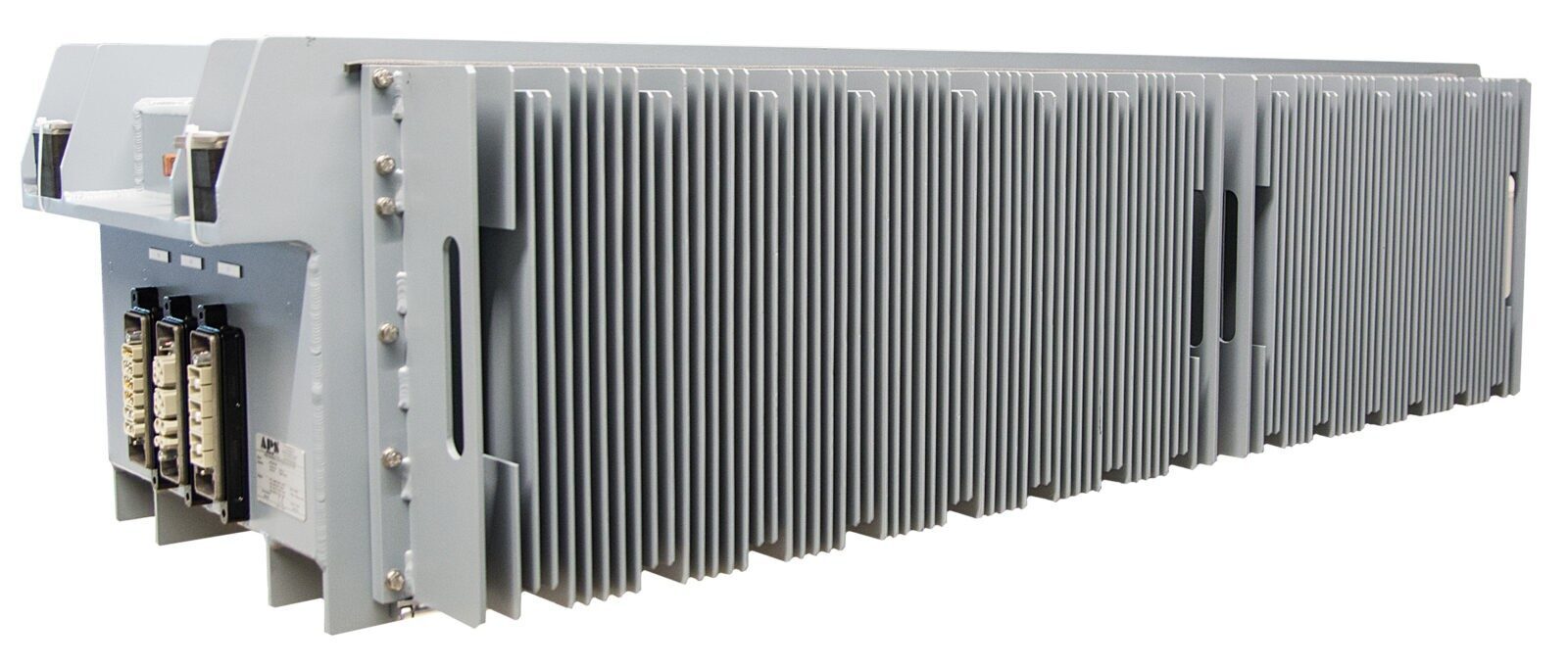
Static converters BFI 50T-TR
Static converter BFI 50T 3000/400/24 TR enables the powering of receivers, independent of the current input voltage.
Product description
The device can be powered by a voltage from the 3×400 V platform network. It allows for both the operation of a 24 V buffer charger and receivers powered by 3×400 voltage installed on the carriage. The second power source
can be the 3,000 V traction network voltage. When connected to the traction network, the following circuits operate: an NPC DC/DC converter lowering the input voltage to 700 VDC, a self-start system, a contactor system allowing for the disconnection of the traction network power supply, an inverter system, and a 24 V buffer charger for charging the main batteries and powering on-board devices.
Thanks to the applied IGBT converter topology, the device features high stability of output voltages and currents, very low output current and voltage ripple, compact dimensions and weight, quiet operation, and high efficiency.
The APS-50 WN TRW MODULE includes, among others: earthing switch, main fuse as a converter protection, soft start system (resistor + contactor), main input contactor, self-start system from the network, and NPC DC/DC converter lowering the input voltage.
The APS-50 NN MODULE includes, among others:
• Inverter system (max. 75 kVA):
– 3×400 VAC – 45 kVA;
– 3×400 VAC – 8 kVA;
– 230 V/50 Hz – max. 10 kVA (option);
• 24 VDC 250 A battery charger with charging current limitation and automatic adjustment of battery charging in a temperature function;
• 24 VDC 50 A battery charger with charging current limitation and automatic adjustment of battery charging in a temperature function (option);
• two 3×400 VAC platform power supply inputs (for left-handed isle unplugged);
• event buffer, which has a parameter logger that collects information about the operating parameters of the converter, its possible damages and faults, and the parameters of the power supply network, with the possibility of reading the parameters from a socket located on the logger. The buffer is built-in in the converter. It is equipped with an output (socket) that allows to assembly inside carriages, e.g. in an electrical cabinet, with a possibility to readout contents by connecting to a computer.
Features
Technical specifications
3,000 VDC, as per UIC550, PK-K-23011:1998
24 V output, In=250 A
• voltage stability ≤1%; voltage ripple ≤0.5%; battery charging function with
voltage temperature compensation.
AC1 – 3×400 VAC/50 Hz/45 kVA (air conditioning):
• voltage stability ≤5%; frequency stability ≤0.2%; harmonic content ≤5%;
overload capacity 200%/5 s; electronic short-circuit protection.
AC2 – 3×400 VAC/50 Hz/8 kVA (laptop sockets, other)
• voltage stability ≤5%; frequency stability ≤0.2%; harmonic content ≤5%;
overload capacity 200%/5 s; electronic short-circuit protection.
Option:
• max. 10 kVA/230 V/50 Hz (from separation transformer supplied from an inverter)
• 24 V output, In=50 A
• voltage stability ≤1%; voltage ripple ≤0.5%; battery charging function with
voltage temperature compensation.
52 kW
+15% power depending on the carriage energy balance
80kW
89%
Alkaline of 24 V / 460–520 Ah capacity
According to UIC 550
According to UIC 550
PN-EN 50121-3-2:2017 Railway applications – Rolling stock – Apparatus, including converter
PN-EN 50121-1:2017 General provisions
PN-EN 50121-2:2017 Relates to the interference emission of the whole railway system
PN-EN 50121-3-1:2017 Railway applications – Train and complete vehicle
PN-EN 50121-3-2:2017 Railway applications – Rolling stock – Apparatus, including converter
Screw terminals on WN can insulators
Quick-couplers
Undercarriage
Natural cooling; external heat sinks on the unit
-25°C up to +40°C
IP56
Suspended, screws, vibration isolators
Powder coating
Aluminium
PN-EN 61373:2011 Railway applications – Rolling stock equipment
Shock and vibration tests
PN-EN 61373:2011 Railway applications – Rolling stock equipment
Shock and vibration tests
500+300 +/- 20% depending on configuration
Automatic
Standard
CANopen
Contact us
You are welcome to contact us if you have questions or are interested in our offer.


